What are the key learning points about simple circuits and Ohm's law?
Current is measured in series with a component using an ammeter.
Voltage is measured across a component using a voltmeter.
Ohm’s Law can be demonstrated for a metal wire, a voltmeter can be used to measure the voltage across the wire and an ammeter to measure the current passing through the wire.
The temperature of the wire is kept constant using a switch and small currents.
A voltage–current characteristic graph (V-I graph) can be plotted, with voltage on the y-axis and current on the x-axis.
The V-I graph is a straight line that passes through the origin, this shows that the current and voltage are When one variable is zero so is the other. As one variable increases the other does at the same rate. When 𝒚 is plotted against 𝒙 this produces a straight-line graph through the origin. for a metal wire at constant temperature, and that this is known as Ohm’s law.
What are standard electric circuit symbols?
An electric circuit is a complete path of conductor from one terminal of a battery to the other.
The following symbols show the different components that can be found in an electrical circuit.
Components
Some of the more common components are:
Switch
A switch is used to turn a circuit on (closed) and off (open).
When the switch is open, there is a break in the circuit and current stops flowing.
Lamp
An electric current heats the filament in a bulb so that it glows white hot and gives out light.
Fixed resistor
A resistor restricts or limits the flow of electrical current.
A fixed resistor has a resistance that does not change.
Variable resistor
Adjusting this resistor changes its resistance.
A variable resistor is used in some dimmer switches and volume controls.
Cell
A chemical reaction occurs inside a cell with chemical energy being converted to electrical energy.
A cell has a positive terminal and a negative terminal.
What is cell polarity?
The symbol for a battery is made by joining two, or more, symbols for a cell together.
These are simple cells.
The type you put in a torch or a TV remote control.
When you join two or more cells together you form a battery – it is a battery of cells.
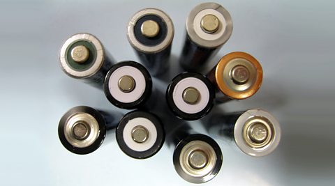
A cell has a positive terminal and a negative terminal.
For cells such as D, AA and AAA, the positive terminal, (+), is the raised end, normally at the top, while the negative terminal, (-), is the flat end, normally at the bottom.
In the circuit diagram of a cell:
- The long line is the positive (+) terminal.
- The short line is the negative (-) terminal.
When cells are joined together to form a battery they are normally joined with the positive terminal of one cell connected to the negative terminal of the next.
The voltage provided by cells connected in series is the sum of the voltages of each cell.
Worked example
What is the voltage of this battery?
Answer
The battery voltage = 1.5 V + 1.5 V + 2.0 V = 5.0 V.
Example
In the example above, one of the cells has been connected the other way round.
The negative terminal of the middle cell is connected to the negative terminal of the first cell.
This causes the voltage of both cells to cancel out, and so the total voltage is now only 1.5 V.
The battery voltage = 1.5 V – 1.5 V + 1.5 V = 1.5 V.
If the polarity of one of the cells is reversed, then the voltage is reduced dramatically.
Cells joined + to + (or - to -) cancel each other out.
Question
What is the voltage of this battery?
Answer
The battery voltage = 3.0V – 1.5 V + 2.0 V = 3.5 V.
What are different examples of circuit diagrams?
1. Series connections
Components that are connected one after another on the same loop of the circuit are connected in series.
Two lamps connected in series
The circuit diagram shows a circuit with two lamps connected in series.
If one lamp breaks, the other lamp will not light.
Series circuits are useful if you want a warning that one of the components in the circuit has failed.
If Christmas tree lights are connected in series they all go out when one bulb breaks.
2. Parallel connections
Components that are connected on separate loops are connected in parallel.
The current is shared between each of the circuit loops.
Two lamps connected in parallel
The circuit diagram shows a circuit with two lamps connected in parallel.
If one lamp breaks, the other lamp will still light.
The lights in most houses are connected in parallel.
This means that if one bulb breaks the others remain on.
For a parallel circuit, the sum of all the current in every branch is equal to the current from the cell.
Question
Which of the circuits here are connected in series, and which are connected in parallel?
Answer
How to measure electric current in series and parallel circuits
A device called an ammeter is used to measure current.
Some types of ammeter have a pointer on a dial, but most modern ammeters have a digital display.
To measure the current flowing through a component in a circuit, you must connect the ammeter in series with it.
Remember, electric current is measured in amperes, or amps for short.
The symbol for amperes is A.
Key points
When measuring current:
current is measured in amperes, A;
the current is measured using an ammeter;
the ammeter must be connected in series.
How to investigate the current flowing in a series circuit
You can investigate current flowing in a series circuit by connecting the following circuit.
Put one ammeter in position A1 and record the reading in a suitable table.
Then move the ammeter to position A2 and repeat and then to position A3.
Results
A1 = 0.8A.
A2 = 0.8A.
A3 = 0.8A.
Conclusion
The current in a series circuit is the same at all places in the circuit.
An electric current is a flow of charged particles.
The particles flow continually right round the circuit and through the cell – there is nowhere else for them to go.
So, the electric current is the same everywhere in a series circuit
Question
Look at the series circuit below:
What is the reading at:
a) Position 1.
b) Position 2.
c) Position 3.
a) Position 1 = 0.1A.
b) Position 2 = 0.1A.
c) Position 3 = 0.1A.
Remember that the charge moves all the way around the circuit and so the current is the same everywhere in a series circuit.
How to investigate the current flowing in a parallel circuit
The current flowing in a parallel circuit can be investigated by connecting the circuit below.
Once more, put one ammeter in position A1 and record the reading in a suitable table.
Then move the ammeter to position A2, A3 and then to A4.
Results:
A1 = 3.2A.
A2 = 1.6A.
A3 = 1.6A.
A4 = 3.2A.
Conclusion
The current in a parallel circuit splits up between the branches of the circuit and then combines again before it goes back into the battery.
The current in each branch adds up to equal the current flowing through the battery.
More current is flowing than for two bulbs in series with two cells – the cells will run down more quickly.
In the diagram, 6 A flows through the cell.
The circuit has three branches, each with an identical lamp, so 2 A flows through each one.
Question
Look at the parallel circuit below, where the lamps are identical:
What is the reading at:
a) Position 1.
b) Position 2.
c) Position 3.
d) Position 4.
Answer
a) Position 1 = 0.2A.
b) Position 2 = 0.1A.
c) Position 3 = 0.2A.
d) Position 4 = 0.1A.
Look carefully where the current splits.
Before the split you get full current.
The current in each branch is less than the full current but then joins back together and adds up to the full current again.
How to measure voltage in circuits
Voltage is marked on cells and electrical components such as bulbs and kettles, but what does it mean?
Key fact
Voltage is a measure of the difference in energy between one part of a circuit and another.
It tells you how much electrical energy has been converted into other forms of energy.
Voltage is measured in volts, V, with a voltmeter.
Voltmeters are always connected in parallel.
This is because it is measuring the difference in energy between the two points it is connected across.
The positive terminal of the voltmeter is connected closest to the positive terminal of the battery.
What are the key points about voltage?
When measuring voltage:
Voltage is measured in volts, V.
Voltage is measured using a voltmeter.
A voltmeter is connected in parallel.
How to measure voltage in a series circuit
You can investigate voltage across cells and lamps in a series and parallel circuit by connecting the following circuits.
Put one voltmeter in position V1 and record the reading in a suitable table.
Then move the voltmeter to position V2 and repeat and then to position V3.
Results
V1 = 3.0V
V2 = 1.5V
V3 = 1.5V
Conclusion
The voltage across each component in a series circuit adds up to equal the voltage across the cells.
How to measure voltage in a parallel circuit
Results
V1 = 3.0V
V2 = 3.0V
V3 = 3.0V
Conclusion
The voltage across each branch of a parallel circuit equals the voltage across the cells.
This shows how to connect a voltmeter for measuring voltage and an ammeter for measuring current.
An ammeter needs to measure the flow of charge, so it is in series.
This means that all the charge has to flow through it and can be counted.
A voltmeter measures voltage across a component.
This means it is in parallel so it can measure the voltage at two different points in the circuit.
Measuring voltage and current can be used to measure .
Key points
For components connected in series:
- The current through each component is the same.
- The voltage of the supply is equal to the sum of the voltages across the separate components.
For components connected in parallel:
- The voltage across each component is the same as that of the supply.
- The total current taken from the supply is the sum of the currents through the separate components.
What is resistance in an electric circuit?
All conductors show some opposition to electric current.
This opposition to current is called resistance.
A good conductor has low resistance.
A poor conductor, or insulator, has high resistance.
The two main ways of increasing the current in an electrical circuit are by increasing the voltage or by decreasing the resistance.
What happens when you change the voltage?
If you increase the voltage across a component, there will be more current in the component.
Too high a voltage and the lamp will break.
What happens when you change the resistance?
If you increase the number of lamps in a series circuit, there will be less current.
The lamps resist the current, so if you put more lamps into the circuit, there is more resistance.
You could increase or decrease the resistance in a circuit by using a variable resistor (also known as a rheostat).
Prescribed practical P1: Ohm's law
How to safely plan and carry out an investigation into Ohm's law
What is the purpose of prescribed practical P1?
To use a voltmeter to measure the voltage across a metal wire and an ammeter to measure the current passing through the wire, and:
demonstrate understanding that the temperature of the wire is kept constant using a switch and small currents.
demonstrate understanding of the need to obtain sufficient values of voltage and current so that a voltage–current characteristic graph (V-I graph) can be plotted, with voltage on the y-axis and current on the x-axis.
recall that the V-I graph is a straight line that passes through the origin.
recall that this shows that the current and voltage are proportional for a metal wire at constant temperature, and that this is known as Ohm’s law.
What are the main variables?
The main variables in a science experiment are the independent variable, the dependent variable and the control variables.
The independent variable is what we change or control in the experiment.
The dependent variable is what we are testing and will be measured in the experiment.
The control variables are what we keep the same during the experiment to make sure it’s a fair test.
In this experiment:
The independent variable is the electric current I.
The dependent variable is the voltage V.
The control variables are the material, length, cross section area and temperature of the wire.
These are kept the same by not changing the wire during the experiment, by keeping the current small and opening the switch in between readings.
Remember - these variables are controlled (or kept the same) because to make it a fair test, only one variable can be changed, which in this case is the current.
What is the prediction for this experiment?
As the current increases, the voltage will also increase.
What is the justification for the prediction?
Greater current will mean that more charge flows.
This means that more energy can be converted from electrical energy to other forms of energy and so voltage increases.
How to manage this experiment safely
| Hazard | Electric shock | Control measures |
|---|---|---|
| Water | Electric shock | Do not set up the experiment near taps, sinks etc. |
| Wire gets hot | Minor burns | Do not handle the wire. Switch off between readings. |
What apparatus is used in prescribed practical P7?
1m length of constantan wire, a metre rule, a low voltage power pack, a variable resistor, a voltmeter, an ammeter, connecting leads, a switch, 2 crocodile clips, Sellotape.
Circuit diagram
How to carry out prescribed practical P7
Set up the circuit, as shown above.
Adjust the variable resistor until the current on the ammeter is 0.1 A. Record the current in a suitable table.
Read the corresponding value of voltage across the wire on the voltmeter and record in the table.
Turn the switch off between all readings to prevent the temperature of the wire rising.
Turn on again. Ensure that the current is still 0.1 A and repeat the voltage reading. Calculate the average voltage.
Repeat the procedure for six more values of current up to 0.7 A.
How to avoid errors when carrying out prescribed practical P7
The temperature of the wire must be kept constant.
Whenever a current flows through a conductor there is a heating effect.
Electrical energy is converted to heat energy.
To ensure the temperature of the wire does not increase, switch off between readings and keep the current as small as possible.
Results
| Current I / A | Voltage V / V | Voltage V / V | Voltage V / V |
|---|---|---|---|
| Reading 1 | Reading 2 | Average voltage | |
| 0.00 | |||
| 0.10 | |||
| 0.20 | |||
| 0.30 | |||
| 0.40 | |||
| 0.50 | |||
| 0.60 | |||
| 0.70 |
Graph
What conclusion can be drawn from an investigation into Ohm's law?
We can see from the graph that as the current increases the voltage also increases.
This agrees with our prediction.
In fact, since the line of best fit is a straight line through the origin, we can be even more precise.
We can say that the voltage across the wire is When one variable is zero so is the other. As one variable increases the other does at the same rate. When 𝒚 is plotted against 𝒙 this produces a straight-line graph through the origin. to the current flowing through it.
As the voltage increases the current increases in direct proportion.
This means that if you double the voltage the current doubles, if you triple the voltage, the current triples, if you halve the voltage, the current halves, and so on.
This is known as Ohm’s Law.
Key facts
Ohm’s law states that the voltage across a conductor is directly proportional to the current flowing through it, provided all physical conditions, such as temperature, remain constant.
A conductor that obeys Ohm’s law is called an ohmic conductor.
Copper or constantan wire are examples of ohmic conductors.
How much do you know about simple circuits and Ohm's law?
More on Electrical circuits
Find out more by working through a topic
- count3 of 5
- count4 of 5

- count5 of 5
- count1 of 5
